Setup & Operating Instructions: Fence Hawk + Plus
Click here to download Fence Hawk + Plus Setup Instructions.pdf
Setup & Operating Instructions: Fence Hawk + PLUS
.
Fence Hawk + Plus
Typical Use:
This unit is designed for security as well as use in pasture and/or farm environment, where the primary function of this fence voltage monitor is to monitor and insure the continuous operation of the electric fence. The Fence Hawk “smart” circuitry eliminates false alarms from lightning, EMP’s, utility voltage variations, and many other causes of false alarms that occur with other fence voltage monitors.
The difference between Fence Hawk and the Fence Hawk * Plus is the addition of a second voltage level sensing circuit. This voltage level sensing circuit is usually set at 1,000 volts so to detect excessive weed growth that shorts out and reduces the effective fence voltage.
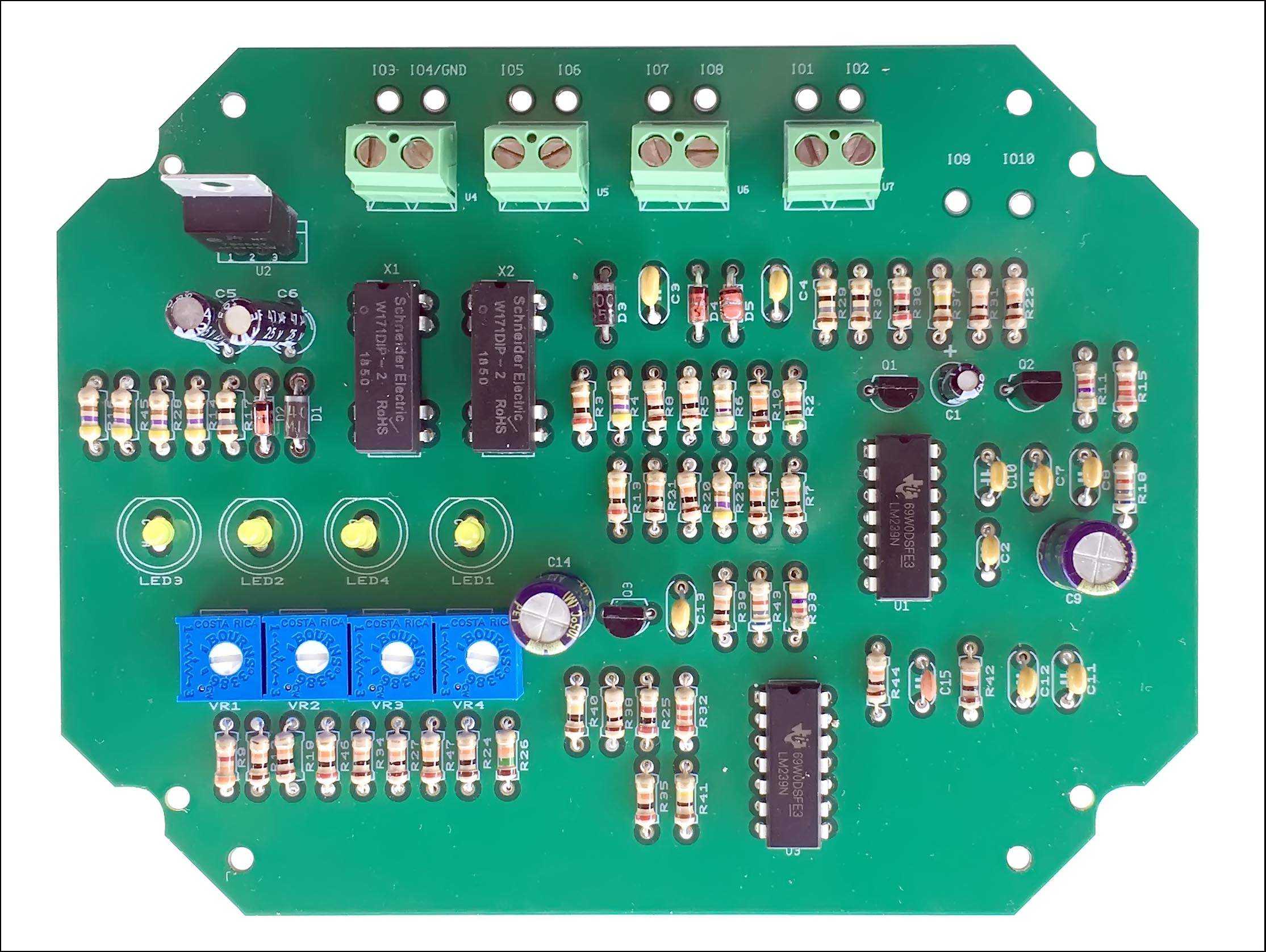
When conditions are met and correct, LED3 will flash with each valid fence voltage pulse that is at, or higher than the fence voltage level that you have set with VR1.
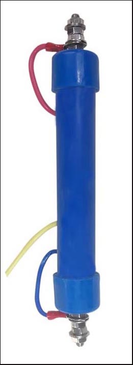
A Remote Voltage Sensor is part of, and included with all Fence Hawks. The voltage sensor is mounted directly on the fence and connected to the Fence Hawk with a single twisted pair (telephone wire or larger). The sensing unit is sealed and the connecting screws and nuts are stainless steel and designed to be mounted directly on fence.
The red wire connection at one end that stands apart from the other two wires is to be connected to the high voltage wire on your fence. The opposite wire on the other end which is to be connected to ground (preferable earth ground). The middle wire is your fence voltage signal wire and the actual voltage on this wire is between 10 to 20 volts. The signal is taken between the middle wire and the ground wire.
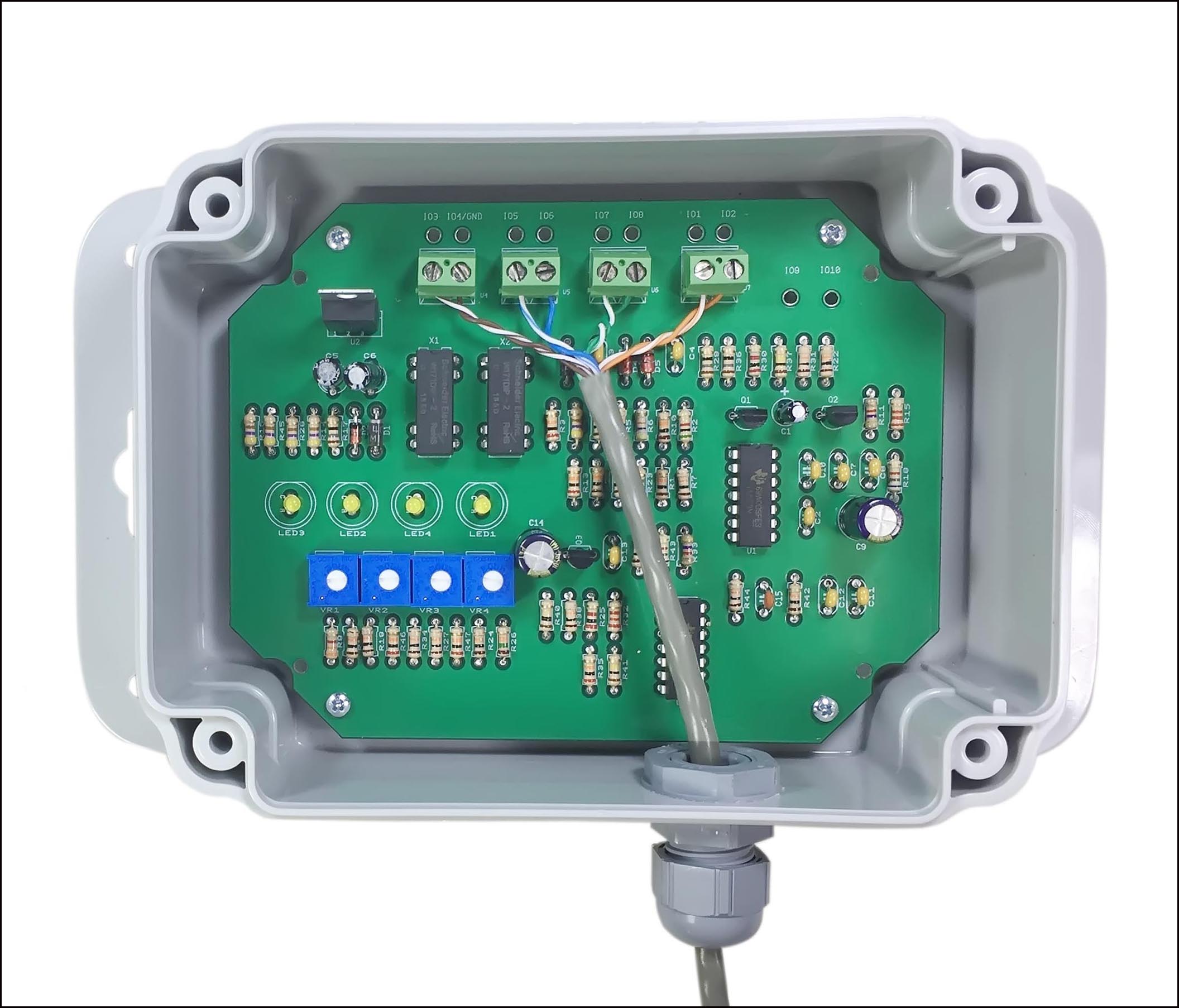
The Remote Voltage Sensor is connected to the Fence Hawk with a simple twisted pair of low voltage wire (ex: telephone wire) that is 26 gage wire or larger. We use an 18 gage twisted pair on the longer distance separations. Depending on the distance between the voltage sensor mounted on your fence and the Fence Hawk unit which can be located from 0 to 2-3 hundred meters/yards away from the voltage sensor hanging on your fence.
The actual working distance between the Fence Voltage Sensor and the Fence Hawk will determine the wire gage of the twisted pair of connecting conductors. Rule of thumb is that bigger is better. The actual pulse voltage that is carried by this pair will range from 5 to 15 volts and cannot be seen of measured by any ordinary voltmeter.
Typical Use: Adjust for your unique fence
The Fence Hawk “smart” circuitry eliminates false alarms from lightning, EMP’s, utility voltage variations, and many other causes of false alarms that occur with other fence voltage monitors. One can determine the actual voltage on any installed fence utilizing the Fence Hawk, and Plus models. VR2, VR3, VR4 are set at the factory and generally do not require adjustment. To achieve the most reliable performance VR1 should be adjusted for each and every fence where it is used.
Generally and typically, the monitoring circuit (VR1/LED3) is set just a 1,000 volts or so below the actual fence voltage and the time delay (VR2/LED2) is set at maximum (> 60 seconds) which allows for wind driven and other temporary voltage changes.
With a digital voltmeter, set on DC voltage where you can read 3 volts DC or less. With the negative probe is inserted in either ground points (IO2 or IO4) and the positive lead is inserted into IO10. Adjust VR1 back and forth until you are at the cusp point where the slightest movement in either direction will either turn on, or turn off the blinking of LED3. This voltage reading time 4444 will be the actual fence voltage. For example; if you are reading 1.8 volts, you allow plus or minus 5% to err on the sage side. Each 1/10 (0.1) volts is equivalent to 444 fence voltage.
Now you have the actual fence voltage for your specific fence. We recommend setting this voltage 0.2 – 0.3 volts lower than the actual fence voltage. The thought is, that when/if the actual fence voltage is reduced where the relay contacts are continuously closed; this is a warning to clean or otherwise repair your fence to bring the fence voltage back to its original level.
VR2 is the adjustment of the time delay before an alarm which closes the connection between terminals IO5 and IO6. This adjustment is set for maximum delay of approximately 90 seconds. Every time the Fence Hawk sees normal voltage, the time delay is reset back to zero and is factory adjusted to maximum time delay. This is set thusly, so blowing foliage does not continuously set off the low voltage alarm.
VR3 sets the time delay for the no-voltage relay contacts to close (IO7 and IO8). This time delay is factory set to minimum delay before closing the no-voltage contacts. Due to the time the circuit takes to analyze the voltage signal from the fence, the delay to close the relay contacts is usually about 4-5 seconds.
When all the fence conditions are met and correct, LED3 will flash with each valid fence voltage pulse that is at, or higher that the fence voltage that you have set as the minimum working voltage for your fence.
VR4 sets the actual voltage when the Fence Hawk Plus goes into no-voltage alarm and closes the on-board relay contacts IO7 and IO8. This voltage can be measured at IO9 and the voltage range is from 200 volts (0.05 volts) to 2,000 volts (0.5 volts).
Click here to download Fence Hawk + Plus Setup Instructions.pdf


